Ordering table
| Feature |
Order data |
Specifications |
Additional information |
| Cable length |
A...
|
01.0 ... 06.0 m, in intervals of 1 m |
|
| |
| Digital interface |
BLD
|
Line Driver (RS422) |
|
|
2xLD
|
2x Line Driver (RS422) |
|
|
O
|
without |
|
| |
| Digital resolution |
C...
|
0.2, 1, 10, 12.5 in µm |
|
| |
| Pulse interval |
D...
|
0.2, 0.5, 1.1, 2.5, 6.3 in µs |
|
| |
| Analog interface |
E1Vss
|
1 VSS |
|
|
O
|
without |
|
| |
Ordering key
ASA110H-A-B-C-D-E-S
Pin assignment
Connector X1
| SSI |
SSI + 2xLD |
PIN |
| nc |
A |
1 |
| nc |
/A |
2 |
| +24 V DC |
+24 V DC |
3 |
| 0 V |
0 V |
4 |
| nc |
nc |
5 |
| nc |
nc |
6 |
| SSI_DATA |
SSI_DATA |
7 |
| /SSI_DATA |
/SSI_DATA |
8 |
| nc |
B |
9 |
| nc |
/B |
10 |
| nc |
nc |
11 |
| SSI_GND |
SSI_GND |
12 |
| nc |
nc |
13 |
| SSI_CLK |
SSI_CLK |
14 |
| /SSI_CLK |
/SSI_CLK |
15 |
Connector X3
| 1 VSS |
PIN |
| sin |
1 |
| /sin |
2 |
| cos |
3 |
| nc |
4 |
| nc |
5 |
| nc |
6 |
| ANA_GND |
7 |
| /cos |
8 |
| nc |
9 |
Connector X2
| RS485 |
RS485 + LD |
PIN |
| nc |
A |
1 |
| nc |
B |
2 |
| nc |
nc |
3 |
| +24 V DC |
+24 V DC |
4 |
| 0 V |
0 V |
5 |
| nc |
/A |
6 |
| nc |
/B |
7 |
| DÜA |
DÜA |
8 |
| DÜB |
DÜB |
9 |
Hint for mounting
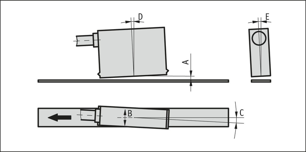
When installing the sensor and magnetic tape, always ensure that both system components are correctly aligned. When mounting, the arrow mark on the tape must point to the same direction as the cable outlet.
| A, Sensor/tape reading distance |
≤0.4 mm |
| B, Lateral offset |
±0.5 mm |
| C, Alignment error |
±1° |
| D, Longitudinal inclination |
±1° |
| E, Lateral inclination |
±2° |

Symbolic representation
Scope of delivery
- ASA110H
- Mounting instructions
- Sensor fastening set