Ordering table
| Feature |
Order data |
Specifications |
Additional information |
| Operating voltage |
A10
|
10.5 … 30 V DC |
|
|
5
|
5 V DC ±5 % |
|
| |
| Design |
BM
|
metal housing with status LEDs |
|
|
ZM
|
metal housing without status LEDs |
|
| |
| Type of connection |
CE1
|
open cable end |
|
|
E6X
|
bullet connector without mating connector |
|
| |
cable extension on request |
|
| |
| Cable length |
D...
|
1 ... 20 m, in steps of 1 m |
|
| |
others on request |
|
| |
| Reference signal |
EO
|
without |
|
|
IA
|
periodic index (analog) |
index signal every 1 mm |
|
ID
|
periodic index (digital) |
index signal every 1 mm |
|
RB
|
fixed, tape side (analog) |
|
|
RD
|
fixed, tape side (digital) |
|
Ordering key
LE100/1-A-B-C-D-E
Pin assignment
Without reference signal
| Signal |
E1 |
E6X |
| GND |
black |
1 |
| sin |
red |
2 |
| /sin |
orange |
3 |
| cos |
yellow |
4 |
| /cos |
green |
5 |
| +UB |
brown |
6 |
| nc |
|
7 |
With reference signal
| Signal |
E1 |
E6X |
| sin |
red |
1 |
| cos |
yellow |
2 |
| index |
blue |
3 |
| +UB |
brown |
4 |
| GND |
black |
5 |
| /sin |
orange |
6 |
| /cos |
green |
7 |
| /index |
violet |
8 |
Hint for mounting
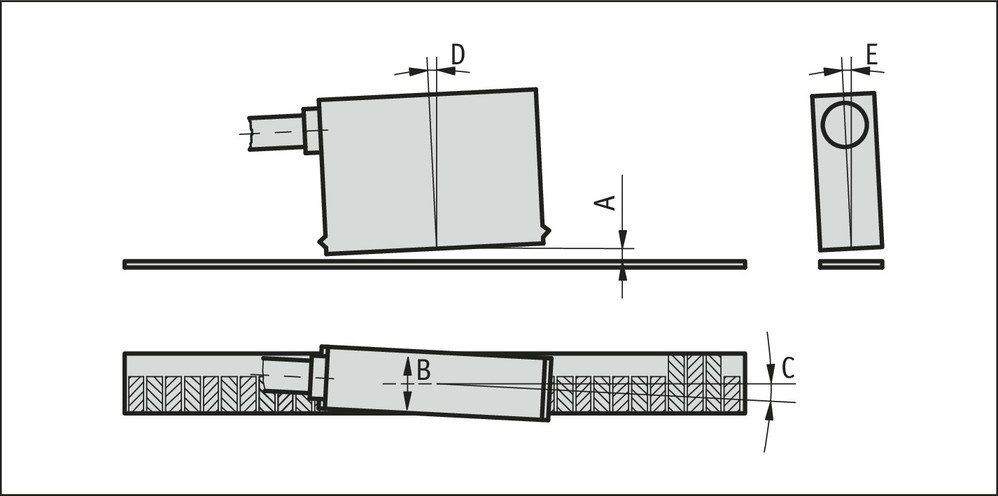
For systems with reference points on the magnetic tape please take care that sensor and strip are correctly aligned (see picture).
| Reference signal |
O, I |
R |
| A, Sensor/tape reading distance |
≤0.4 mm |
≤0.2 mm |
| B, Lateral offset |
±2 mm |
±0.5 mm |
| C, Alignment error |
±3° |
±3° |
| D, Longitudinal inclination |
±1° |
±1° |
| E, Lateral inclination |
±3° |
±3° |

(symbolic sensor representation)

symbolic sensor representation
Scope of delivery
- LE100/1
- Quick Start Guide
- Fastening set