Mechanical data
| Feature |
Technical data |
Additional information |
| Housing |
zinc die-cast / aluminum |
M design: aluminum front cover |
| |
zinc die-cast
|
ZM design
|
| Sensor/band reading distance |
0.1 … 0.4 mm |
O, I reference signals |
| |
0.1 … 0.2 mm |
RB reference signal
|
| Cable sheath |
PUR suitable for drag-chain use
|
6, 8-wire ø5-0.4 mm
|
| Cable bending radius |
5x cable diameter |
static |
| |
7.5x cable diameter |
dynamic |
| Service life of cable |
>5 million cycles |
under the following test conditions:
travel range 4.5 m
travel speed 3 m/s
acceleration 5 m/s2
ambient temperature 20 °C ±5 °C |
Travel speed
| |
|
Travel speed Vmax [m/s] |
| Resolution [µm] |
0.2 |
0.64 |
0.32 |
0.16 |
0.08 |
| 1 |
3.20 |
1.60 |
0.80 |
0.40 |
| 2 |
6.40 |
3.20 |
1.60 |
0.80 |
| 5 |
16.00 |
8.00 |
4.00 |
2.00 |
| Pulse interval [μs] |
0.25 |
0.50 |
1.00 |
2.00 |
| Counting frequency [kHz] |
1000.00 |
500.00 |
250.00 |
125.00 |
Electrical data
| Feature |
Technical data |
Additional information |
| Operating voltage |
6.5 … 30 V DC |
reverse polarity protected
|
| |
4.75 … 6 V DC |
no reverse polarity protection
|
| Current consumption |
<25 mA |
unloaded |
| Output circuit |
LD (RS422) |
|
| Output signals |
A, /A, B, /B, I, /I or R, /R
|
|
| Output signal level high |
>2.5 V |
|
| Output signal level low |
<0.5 V |
|
| Latency |
1.5 µs |
|
| Pulse width of reference signal |
1 or 4 increment(s) |
|
| Real-time requirement |
speed-proportional signal output
|
|
| Type of connection |
open cable end
|
|
| |
plug connector
|
7/8-pole
|
| |
D-Sub |
9-pole
|
Signal pattern

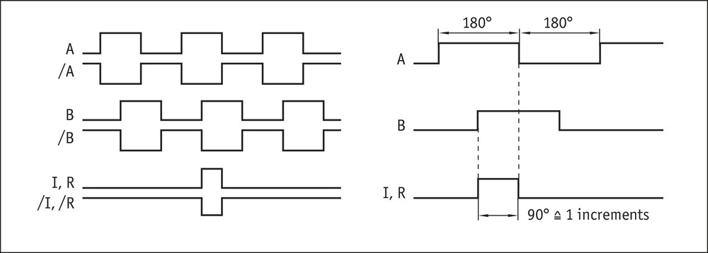
 The logical condition of signals A and B is not defined in reference to the index signal I or the reference signal R. It can deviate from the signal form.
 Reference or index signal with 4 increments (360°) signal length is only valid from the 5th counting step onwards. A corresponding delay should be taken into consideration after switching on the operating voltage.
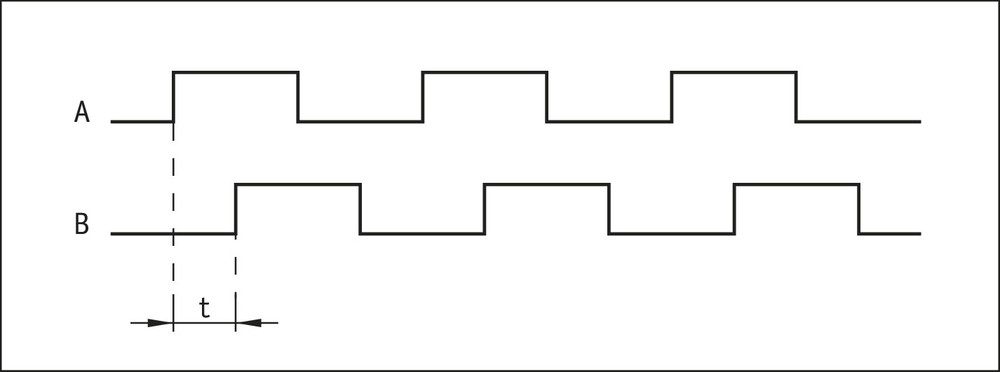
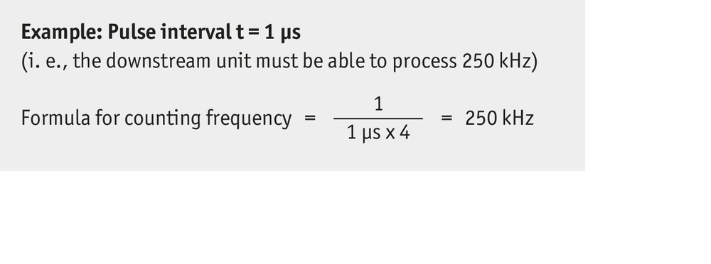
Pulse interval


System data
| Feature |
Technical data |
Additional information |
| Resolution |
0.2, 1, 2, 5 µm |
|
| Linearity deviation |
±2 µm |
at TU = 20° C, reading distance 0.2 mm
|
| Repeat accuracy |
±1 µm |
|
| Measuring range |
∞ |
|
| Travel speed |
depending on resolution and pulse interval |
see table |
Ambient conditions
| Feature |
Technical data |
Additional information |
| Ambient temperature |
-10 … 70 °C |
|
| Storage temperature |
-30 … 80 °C |
|
| Relative humidity |
100 % |
condensation admissible |
| EMC |
EN 61000-6-2 |
interference resistance / immission |
| |
EN 61000-6-4 |
emitted interference / emission
|
| Protection category |
IP67 |
EN 60529 |
| Shock resistance |
500 m/s2, 11 ms |
EN 60068-2-27
|
| Vibration resistance |
100 m/s2, 5 … 150 Hz |
EN 60068-2-6 |