Siko Magnetic sensor MSA
Product Information
Profile MSA:
To be connected to magnetic displays MA505 and MA561
Max. resolution depends on downstream electronics unit
Repeat accuracy depends on downstream electronics unit
Reading distance ≤1 mm
Max. measuring length 5120 mm
Mechanical data
| Feature | Technical data | Additional information |
|---|---|---|
| Housing |
aluminum uncoated chromated |
|
| Sensor/band reading distance | ≤1 mm | |
| Cable sheath | PVC |
Electrical data
| Feature | Technical data | Additional information |
|---|---|---|
| Operating voltage |
supply via downstream electronic unit |
|
| Current consumption | see downstream electronics | |
| Type of connection | D-Sub |
9-pole, 1x pin (E8 type of connection) |
|
mini-DIN |
8-polig, 1x Stift (Anschlussart E10) |
System data
| Feature | Technical data | Additional information |
|---|---|---|
| Resolution |
depending on display / downstream electronic unit |
|
| System accuracy |
±(0.05 + 0.03 x L) mm, L in m |
at TU = 20 °C |
| Repeat accuracy | 0.01 mm | |
| Measuring range | ≤5120 mm | |
| Travel speed | ≤5 m/s |
Ambient conditions
| Feature | Technical data | Additional information |
|---|---|---|
| Ambient temperature | 0 … 60 °C | |
| Storage temperature | -20 … 80 °C | |
| Relative humidity | 100 % | condensation admissible |
| Protection category | IP67 |
EN 60529 (sensor head) |
| Shock resistance | 500 m/s2, 11 ms |
EN 60068-2-27 |
| Vibration resistance | 100 m/s2, 5 … 150 Hz | EN 60068-2-6 |
Ordering table
| Feature | Order data | Specifications | Additional information |
|---|---|---|---|
| Type of connection |
AE8 |
D-SUB | |
|
E10 |
mini-DIN connector | ||
| Cable length |
B… |
01.0 … 20 m, in intervals of 1 m | |
| others on request | |||
Ordering key
MSA-A-I-A-B
For more information, click here!
Pin assignment
| Signal | PIN E8 | PIN E10 |
|---|---|---|
| nc | 1 | 2 |
| LK14A | 2 | 1 |
| SENS DATA | 3 | 3 |
| LK14B | 4 | 5 |
| nc | 5 | |
| CLK | 6 | 4 |
| +5V | 7 | 8 |
| GND | 8 | 6 |
| STR | 9 | 7 |
Hint for mounting
When mounting sensor and magnetic tape, please be careful to align both system components correctly. The arrow marks on the tape and sensor must point in the same direction when mounting the components.
| A, Sensor/tape reading distance | ≤1 mm |
| B, Lateral offset | ±1 mm |
| C, Alignment error | ±2° |
| D, Longitudinal tilt | ±1° |
| E, Lateral tilt | ±3° |

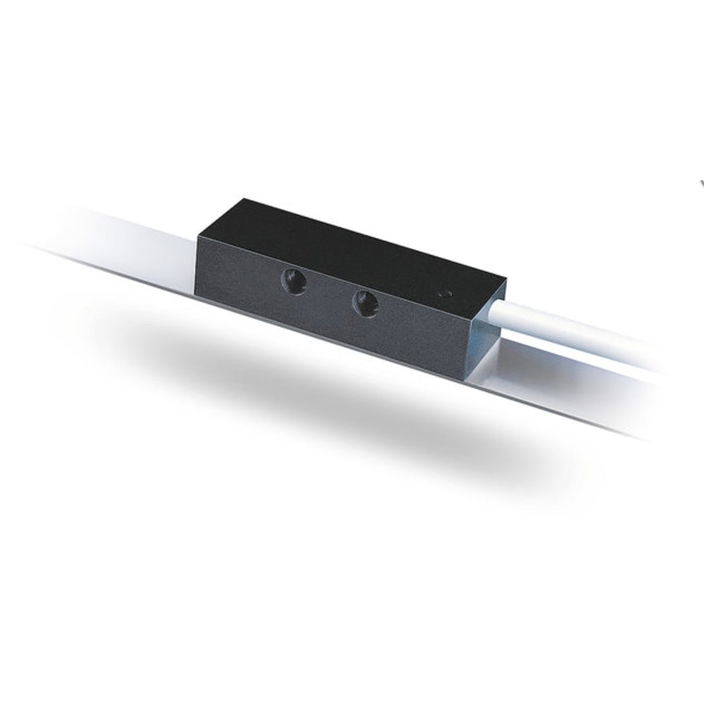
symbolic sensor representation
Scope of delivery
- MSA
- User information
- Fastening set
- snap ferrite on sensor cable
