Siko AP10

Product Information
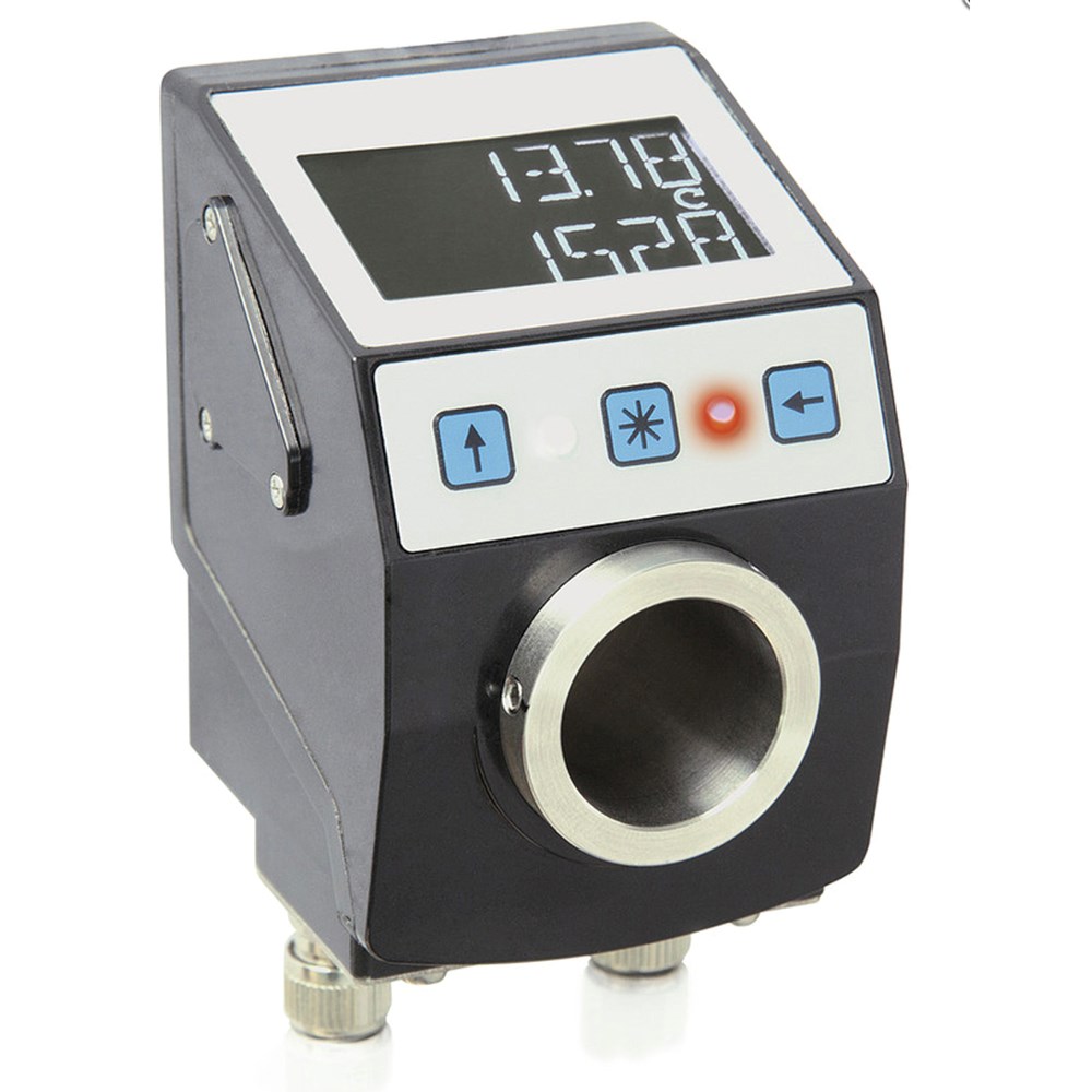
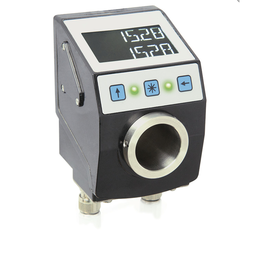
Electronic position indicator AP10
With interface
The AP10 position indicator with communication interface is used for monitored format adjustment to reduce setup times and increase machine efficiency. Readability is optimized for intuitive user prompting: The backlit display clearly shows the setpoint and actual value, and the two LEDs clearly indicate the direction in which the adjustment must be made. The IO link interface enables easy and reliable integration into modular machines
- Electronic position indicator with interface
- Stainless-steel hollow shaft ø20 mm, up to ø25.4 mm as an option
- Backlit display
- Two-line LCD for target and actual values
- Reset, incremental measurement, offset via keyboard
- Integrated RS485 interface, CAN bus or IO-Link as an option
- Robust sensor technology unit thanks to magnetic scanning
- User guidance through status LEDs
- Mechanically compatible with the DA09S position indicator
- IP53 type of protection, IP65 as an option
- Industry 4.0 ready
Mechanical data
| Feature | Technical data | Additional information |
|---|---|---|
| Shaft | stainless steel | |
| Housing | reinforced plastic | plug thread, nickel-plated brass/cover, metal ground connection |
| Color |
black, RAL 9005 |
|
| Speed | ≤500 rpm | |
| Weight | ~0.2 kg |
Electrical Data
| Feature | Technical data | Additional information |
|---|---|---|
| Operating voltage | 24 V DC ±20 % | |
| Current consumption | ~30 mA |
additional ~3 mA per LED when operated with LEDs |
| Power input | ~0.72 VA | Max. power supply of the power supply unit used: 100 VA. The power supply used corresponds to SELV/Limited Energy (IEC 61010-1) or SELV/LPS (IEC 60950-1) or Class 2 (UL 1310). |
| Battery service life | ~5 year(s) | |
| Parameter storage | 105 cycles | also applies to calibration operations |
| Display/display range | 6-digit LCD 14-segment, ~8 mm height | decimal points, 2 rows, special characters (backlit LED red/white) |
| Special character |
cw arrow, ccw arrow, incremental measurement, battery |
|
| Status display |
2x two-color LED (red/green) |
position status, configurable |
| Keys |
incremental measurement function, parameterizing, resetting |
|
| Interface | RS485; CANopen; IO Link | no galvanic isolation |
| Type of connection |
2x M8-plug connectors (A-coded) |
4-pin, 1x socket, 1x pin (RS485, CANopen) |
| 1x M8 connector (A-coded) | 4-pin, 1x pin (IO-Link) | |
|
grounding via flat male tab 6.3 mm or terminal lug |
System data
| Feature | Technical data | Additional information |
|---|---|---|
| Scanning |
magnetic |
|
| Resolution | 880 increments/revolution | displayed value/rotation freely configurable |
| Measuring range | ≤11914 revolution(s) | |
| Approval | UL | UL 61010-1, File No. E503367 |
Ambient conditions
| Feature | Technical data | Additional information |
|---|---|---|
| Ambient temperature | 0 … 60 °C | |
| Storage temperature | -20 … 80 °C | |
| Relative humidity | condensation inadmissible | |
| EMC | EN 61326-1 | Industry immunity requirement, class B emission limit |
| Safety regulations | DIN EN 61010-1 (VDE 0411-1), UL 61010-1 | Limited power supply according to DIN EN 61010-1 Section 9.4. Protection class II Surge category II Pollution level 2 |
| Protection category | IP53 |
EN 60529, only with mating connector (protection class not examined by UL) |
| IP65 |
EN 60529, only with mating connector (protection class not examined by UL) |
|
| Shock resistance | 500 m/s2, 11 ms |
EN 60068-2-27 |
| Vibration resistance | 100 m/s2, 5 … 150 Hz |
EN 60068-2-6 |

For more information, please click here!
Ordering table
| Feature | Order data | Specifications | Additional information |
|---|---|---|---|
| Interface/protocol |
ACAN |
CANopen | |
|
S3/09 |
RS485/SIKONETZ5 | ||
|
IOL |
IO Link | ||
| Hollow shaft/diameter |
B20 |
ø20 mm | |
|
25.4 |
ø25.4 mm | ||
| Torque pin/position |
CII |
30 mm distance | |
|
I |
22 mm distance | optional | |
| Protection category |
DIP53 |
IP53 | |
|
IP65 |
IP65 | ||
| Viewing window |
ESF |
front foil | |
|
K |
plastic | impact protection | |
Ordering key
AP10-A-B-A-C-D-EX-E-S
Pin Assignment
Interfaces
| RS485 | CAN-Bus | IO-Link | PIN |
|---|---|---|---|
| TxRx-/DÜB | CANL | L+ (+UB) | 1 |
| TxRx+/DÜA | CANH | nc | 2 |
| +UB | +UB | L- (GND) | 3 |
| GND | GND | C/Q | 4 |
In most cases, data exchange with the position indicators is limited to the exchange of process data. In addition to the process data, intelligent displays provide additional information that can be evaluated for condition monitoring up to predictive maintenance:
| Process Data | Smart Value | Smart Function |
|---|---|---|
| Actual position | Battery voltage | Battery change planning |
| Target position | Speed | Overload |
Scope of delivery
- AP10
- Mounting instructions