{{image.AltTag}} {{image.AltTag}}
Default Image Default Image

{{details.product.ModelName}}

Sku: {{details.product.ModelNumber}}

Siko Absolute, SSI interface, CANopen, resolution 1 μm
{{details.product.PriceUnits}}
Please fill out this field...
Please enter a number...
Please enter at least 1...
Please enter at max 999999...

You purchased this item on {{details.product.OrderHistory[0].OrderDate | date : 'yyyy-MM-dd'}}
  • Max. resolution of 5 μm absolute, 1 μm incremental
  • Repeat accuracy of 0.005 mm
  • SSI, RS485, CANopen output circuits
  • Additional incremental signals LD as an option (SSI, RS485)
  • Reading distance ≤1.3 mm
  • Max. measuring length 10240 mm
  • Status LEDs for diagnosis

Mechanical data

Feature

Technical data

Additional information

Housing

zinc die-cast


Sensor/band reading distance

≤1.3 mm


Electrical data

Feature

Technical data

Additional information

Operating voltage

4.5 … 30 V DC

reverse polarity protected

Power input

<1.5 W


SSI clock speed input

≤750 kHz

depending in cable length

Output circuit

without, LD (RS422)


Interface

SSI, RS485


CANopen

spec. 2.0A, DS 301, DS 406, ISO 11898

Baud rate

0.05 … 1 MBit/s

CANopen

Cycle time

<25 µs

SSI/RS485


<40 µs

CANopen

Type of connection

M12 plug connector (A-coded)

12-pole, 1x pin


M12 plug connector (A-coded)

5 poles, 1x pin (CANopen)

System data

Feature

Technical data

Additional information

Resolution

5, 10 µm

absolute


10 µm

absolute, CANopen factory setting, reconfigurable to 5 µm


1, 5, 10 µm

incremental

System accuracy

±(0.02 + 0.03 x L) mm, L in m

bei TU = 20 °C

Repeat accuracy 

≤5 µm

; ±1 digit

at TU = 20 °C

Measuring range

≤10240 mm


Travel speed

≤5 m/s

absolute


see table

incremental

Travel speed incremental 


Travel speed Vmax [m/s]

Resolution [mm]

0.001

4.00

1.60

0.80

0.32

0.20

0.10

0.05

0.03

0.01

0.005

20.00

8.00

4.00

1.60

1.00

0.50

0.25

0.13

0.06

0.010

25.00

16.00

8.00

3.20

2.00

1.00

0.50

0.25

0.13

Pulse interval [μs]

0.20

0.50

1.00

2.50

4.00

8.00

16.00

32.00

66.00

Counting frequency [kHz]

1250.00

500.00

250.00

100.00

62.50

31.25

15.63

7.81

3.79

Ambient conditions

Feature

Technical data

Additional information

Ambient temperature

-30 … 85 °C


Storage temperature

-40 … 85 °C


Relative humidity

100 %

condensation admissible

EMC

EN 61000-6-2

interference resistance / immission


EN 61000-6-4

emitted interference / emission

Protection category

IP67

EN 60529, mating connector mounted

Shock resistance

500 m/s2, 11 ms

EN 60068-2-27

Vibration resistance

100 m/s2, 5 … 150 Hz

EN 60068-2-6


Ordering table

Order Key Place

Feature

Order data

Specifications

Additional information

A

Interface
 

ARS485

SIKONETZ3


SSI

SSI, RS422


CAN

CANopen


B

Absolute resolution

B5

5 µm


10

10 µm

CANopen factory setting

C

Output circuit

CO

without LD


LD

LD, RS422 incremental

only with SSI, RS485

D

Incremental resolution

D1

1 µm

only with LD output circuit

5

5 µm

only with LD output circuit

10

10 µm

only with LD output circuit

E

Pulse interval

E...

0.2, 0.5, 1.0, 2.5, 4.0, 8.0, 16.0, 32.0, 66.0 in µs


Ordering key

SIK-MSA501 – A – B – C – D – E - S

For more information please, click here

Pin assignment

SSI, RS485 without LD

SSI RS485 PIN
nc nc 1
D+ DÜA 2
D- DÜB 3
T- nc 4
+UB +UB 5
nc nc 6
nc nc 7
nc nc 8
nc nc 9
config config 10
T+ nc 11
GND GND 12

CANopen

Signal PIN
CAN_GND* 1
+UB 2
GND* 3
CAN_H 4
CAN_L 5

CAN_GND internally connected to GND

SSI, RS485 with LD

SSI RS485 PIN
nc nc 1
D+ DÜA 2
D- DÜB 3
T- nc 4
+UB +UB 5
/A /A 6
A A 7
/B /B 8
B B 9
config config 10
T+ nc 11
GND GND 12

Industry 4.0

In most cases, data exchange with the magnetic encoders is limited to the exchange of process data. In addition to the process data, intelligent drives provide additional information that can be evaluated for condition monitoring up to predictive maintenance:

Process Data Smart Value Smart Function
Actual position
Speed
-- Plausibility monitoring

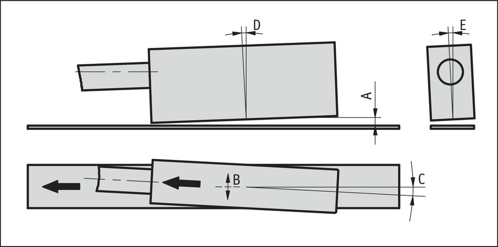
Hint for mounting

When mounting sensor and magnetic tape, please be careful to align both system components correctly. The arrow marks on the tape and sensor must point in the same direction when mounting the components.

A, Sensor/tape reading distance ≤1.3 mm
B, Lateral offset ±3 mm
C, Alignment error ±1.5°
D, Longitudinal tilt ±1°
E, Lateral tilt ±4°

MSA501 Hint for mounting
symbolic sensor representation

Scope of delivery

  • MSA501
  • Mounting instructions
  • Fastening set