{{image.AltTag}} {{image.AltTag}}
Default Image Default Image

{{details.product.ModelName}}

Sku: {{details.product.ModelNumber}}

Siko Absolute high-resolution, numerous interfaces, very small design
{{details.product.PriceUnits}}
Please fill out this field...
Please enter a number...
Please enter at least 1...
Please enter at max 999999...

You purchased this item on {{details.product.OrderHistory[0].OrderDate | date : 'yyyy-MM-dd'}}
  • High absolute resolution 1 μm
  • Repeat accuracy max. ±1 μm
  • Reading distance ≤0.8 mm
  • Measuring range 0 ... 16 m
  • Function and status display LED
  • Interface BiSS C, SSI, IO-Link
  • Optionally analog Sin/Cos 1 Vss or digital line driver
  • Industry 4.0 ready<

Mechanical data

Feature Technical data Additional information
Housing

zinc die-cast

 
Sensor/band reading distance ≤0.8 mm  
Cable length 1 … 20 m (connection type E1) 
Cable sheath PUR, suitable for drag-chain use 10-core ø5.5-0.4 mm (E1, twisted in pairs)
Cable bending radius 28 mm static
  42 mm

dynamic

Service life of cable 5 million cycles under the following test conditions:
Travel distance 4.5 m
Travel speed 3 m/s
Acceleration 5 m/s2
Ambient temperature 20° C ± 5° C
Weight ~0.05 kg without cable

Electrical data

Feature Technical data Additional information
Operating voltage 4.5 … 30 V DC

reverse polarity protected (SSI + BISS/C)

  7.5 … 30 V DC reverse polarity protected (IOL) 
Current consumption <200 mA  
Status display RGB-LED plausibility error, distance warning, device status
Output circuit without, LD, 1Vss  
Interface SSI, BiSS C, IO Link  
Real-time requirement speed-proportional signal output Sin/Cos output
Type of connection

open cable end

(SSI + BISS/C)
  M12 connector (A-coded) 4-pole, 1x pin (IOL)

Signal pattern, Sin/Cos output 

MSA213C Signal pattern, Sin/Cos output

E: reference voltage 2.5 V
F: 1 VSS ±10%
M: 90° ±1.0° / ±3° (25 kHz) 

Signal pattern, LD output circuit 

MSA213C Signal pattern, LD output circuit

Pulse interval, LD output circuit 

MSA213C Pulse interval, LD output circuit

MSA213C

System data

Feature Technical data Additional information
Pole length 2 mm incremental
Resolution 1 µm absolute
  1, 5, 10 µm LD, incremental 
  2 mm period length, 1Vpp
Linearity deviation ±10 µm  
Repeat accuracy  ±1 µm  
Measuring range ≤16000 mm  
Travel speed ≤5 m/s absolute
  ≤25 m/s incremental

Travel speed, LD output circuit 

    Travel speed Vmax [m/s]
Resolution [µm] 1 10.00 5.00 2.00 1.00 0.50 0.20
5 25.00 25.00 10.00 5.00 2.50 1.00
10 25.00 25.00 20.00 10.00 5.00 2.00
Pulse interval [μs] 0.10 0.20 0.50 1.00 2.00 5.00
Counting frequency [kHz] 2500.00 1250.00 500.00 250.00 125.00 50.00

Ambient conditions

Feature Technical data Additional information
Ambient temperature -40 … 85 °C  
Storage temperature -40 … 85 °C  
Relative humidity 100 % condensation admissible
EMC EN 61326-1 industry immunity requirement, class B emission limit
Protection category IP67 EN 60529
Shock resistance ≤500 m/s2, 11 ms EN 60068-2-27, half-sine, 3 axes (+/-), each 3 pulses 
Vibration resistance ≤100 m/s2, 10 … 2000 Hz

EN 60068-2-6, 3 axes, each 10 cycles

Magnetic sensor MSA213C

Ordering table
Feature Order data Specifications Additional information
Type of connection

AE1

open cable end only with SSI, BISS/C

E12X

plug outlet with cable only with IO-link
Cable length L

B...

01.0 ... 20.0 m, in intervals of 1 m only at E1

00.3

0.3 m only at E12X
  others on request  
Interface

CBiSS/C

BiSS C only at E1

SSI

RS422 only at E1
Output circuit

D1Vss

Sin/Cos only at E1

LD

Line Driver (RS422) only at E1

O

without  
Incremental resolution

E...

1, 5, 10 in µm only with LD
  no information required  
Pulse interval

F...

0.1, 0.2, 0.5, 1, 2, 5 in µs only with LD
  no information required  
Ordering key

MSA213C-A-B-C-D-E-F-S

For more information please click here

Pin assignment 

Interface SSI, BiSS C without LD, 1Vss 

SSI BiSS C Cable colour
GND GND black
+UB +UB bown
nc nc red
nc nc yellow
nc nc orange
nc nc green
T+ MA blue
T- NMA violet
D+ SLO gray
D- NSLO white

Interface IO-Link 

Signal PIN
L+ (+UB) 1
I/Q 2
L- (GND) 3
C/Q 4

Interface SSI, BiSS C with LD, 1Vss 

SSI BiSS C Cable color
GND GND black
+UB +UB brown
A, Sin+ A, Sin+ red
/A, Sin- /A, Sin- yellow
B, Cos+ B, Cos+ orange
/B, Cos- /B, Cos- green
T+ MA blue
T- NMA violet
D+ SLO gray
D- NSLO white
Industry 4.0 

In most cases, data exchange with the magnetic encoders is limited to the exchange of process data. In addition to the process data, intelligent drives provide additional information that can be evaluated for condition monitoring up to predictive maintenance: 

Process Data Smart Value Smart Function
Actual position -- Plausibility monitoring

Hint for mounting 

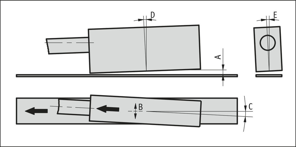
When you mount the sensor and magnetic tape, please be careful to align both system components correctly. The arrow marks on the tape and sensor must point in the same direction when mounting the components. 

A, Sensor/tape reading distance ≤0.8 mm
B, Lateral offset ±0.6 mm
C, Alignment error ±1°
D, Longitudinal tilt max. sensor/tape A reading distance must never be exceeded.
E, Lateral tilt max. sensor/tape A reading distance must never be exceeded.

MSA213C Hint for mounting
Symbolic representation